Four Common Topological Approaches to Powering LEDs
There are many topologies that can be used to power LEDs. As you probably already know, you need to first identify your design requirements before you start selecting, or you may end up with a design that is less than ideal or, worse, not guaranteed to work properly over the long term. For example, when driving one or more LEDs, the minimum and maximum forward voltage drops of the LEDs, the current level, and the operating temperature determine the required converter output voltage range. For example, when looking at the datasheet of a typical red LED, I found that the forward voltage drop varies by 35% at its ideal driver current. If the LED manufacturer "groups" or "bins" the parts for forward voltage, the variation drops to a more reasonable 6%. In addition, the relative forward voltage drop can vary by 13% with operating temperature, and the set current selected for the LED can help increase this variation by 16%.
So what does all this mean? Once you have this information, you need to determine the minimum and maximum output voltage of the converter. This is simply the total of all the LED forward voltage drops added to the voltage across the sense resistor. The converter input voltage range determines whether the output voltage is always higher, lower, or somewhere in between.

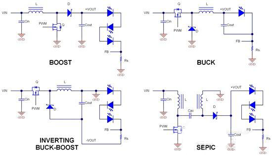
Four Common Topologies for Powering LEDs
Boost
As the name implies, the boost converter output is always greater than its input voltage and is generally the most efficient of the converters shown above. Advantages include clamping the FET voltage (which minimizes hum and noise) and low input ripple current (allowing for small input capacitors). Disadvantages are higher currents in the inductor, FET, and diode (higher than the output), potentially greater losses in the FET due to high voltage switching and higher currents, and pulsating currents in the output capacitor. These disadvantages are usually insignificant if the output current is much less than 1A.
Buck
When driving a small number of LEDs from a higher input voltage, a buck converter should be selected. It generally achieves very high efficiency with the smallest overall package size. Advantages include component stress of less than or equal to Vin max and less than or equal to Iout, and low output ripple current (allowing for small output capacitors). The downside is pulsating input current and possible ringing noise at the FET switch voltage. A good practice is to place the output capacitor in parallel with the LED (rather than at ground) to simplify the control loop.
Inverting Buck-Boost
The inverting buck-boost is an “in between” topology option, meaning the converter can be used as either a buck or a boost. Even if the output is negative, the LED doesn’t really care and doesn’t need to stop. Since the controller is referenced to –Vout, the connections for the current sense resistor feedback are similar to the standard buck topology. In fact, it’s often hard to tell the difference from the buck topology because many of the connections are the same, but the circuit operation is different. The advantages include using a buck (or synchronous buck) controller and getting buck-boost functionality! The disadvantages are lower efficiency, higher current levels (similar to the boost topology), and level shifting if you need to get the controller enabled.
SEPIC
The single-ended primary inductor converter (SEPIC) is a non-inverting buck-boost topology. The inductor can be either coupled (like a transformer) or completely discrete. Advantages include clamped switch operation similar to a boost converter (ideal for low noise, high switching frequency) and low input ripple current (good for small input capacitors). Disadvantages are the highest component count, lower efficiency, highest current stress, and the most complex control loop that is hard to understand (but generally not a problem at lower bandwidths).


