
STM32F469VGT6: High-performance microcontroller for computing and graphics processing
STMicroelectronics' STM32F469VGT6 is a high-performance ARM Cortex-M4 microcontroller, belonging to the STM32F4 series. It is designed for applications that require high computing performance, rich peripherals and graphics processing capabilities, and is widely used in embedded systems, industrial control, consumer electronics and graphics display.
STM32F469VGT6 Introduction
Core parameters
Core: Based on the ARM Cortex - M4 32-bit RISC core, with a floating point unit (FPU) single precision, supports all ARM single-precision data processing instructions and data types, and also implements a full set of DSP instructions and memory protection unit (MPU), operating frequency up to 180MHz, providing 225DMIPS processing power.
Memory: Contains high-speed embedded memory, flash memory up to 2MB, SRAM up to 384KB, and backup SRAM up to 4KB.
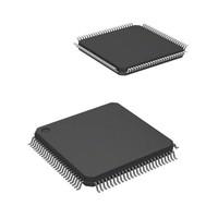
Package: Adopts LQFP - 100 package, with good electrical performance and mechanical stability, easy to install and solder on the circuit board.
Peripheral resources
Communication interface: It has a rich set of communication interfaces, including multiple I²C interfaces, USARTs, UARTs, SPIs, SAI, CAN, SDIO, USB 2.0 high-speed/full-speed device/host/OTG controllers, 10/100 Ethernet MAC, etc., which can easily communicate and connect with other devices.
Graphics processing: It integrates the Chrom-ART Accelerator graphics hardware accelerator, supports LCD parallel interface (8080/6800 mode), LCD TFT controller (supports up to XGA resolution) and MIPI DSI host controller (supports up to 720p 30Hz resolution), which can effectively reduce the CPU's burden on graphics processing and improve graphics display performance.
Other peripherals: Provide three 12-bit ADCs, two DACs, a low-power RTC, twelve general-purpose 16-bit timers (including two PWM timers for motor control), two general-purpose 32-bit timers and a true random number generator (RNG) to meet the different needs of various application scenarios.
Electrical characteristics
Operating voltage: The voltage range is 1.7V to 3.6V, with a wide voltage adaptation range, which can adapt to different power supply conditions.
Operating temperature: The operating temperature range is - 40°C to 85°C, which can meet the ambient temperature requirements of various industrial and consumer applications.
Application areas
Industrial control: With its rich interfaces and powerful processing capabilities, it can be used in industrial automation equipment, motor control, programmable logic controllers (PLCs) and other fields to achieve precise control and monitoring of industrial processes.
Consumer electronics: In consumer electronic devices such as smart home appliances and digital products, it can be used to implement complex control logic, graphical interface display and human-computer interaction functions to enhance the user experience of products.
Medical equipment: Suitable for some medical equipment with high reliability and performance requirements, such as medical monitoring instruments, portable medical devices, etc., for data collection, processing and control.
IoT devices: Rich communication interfaces enable it to be easily connected to various sensors and actuators. It can be used as the core controller of the IoT node to achieve interconnection and intelligent management between devices.
Product Comparison
STM32F469VGT6 similar or alternative parts
STM32F469VGT6 vs STM32L476RGT6 vs ATSAM4S16CA-AU vs ATSAM4E16CA-AU vs ATSAME70N20A-AN
| Parameter | STM32F469VGT6 | STM32L476RGT6 | ATSAM4S16CA-AU | ATSAM4E16CA-AU | ATSAME70N20A-AN |
|---|---|---|---|---|---|
| Image | 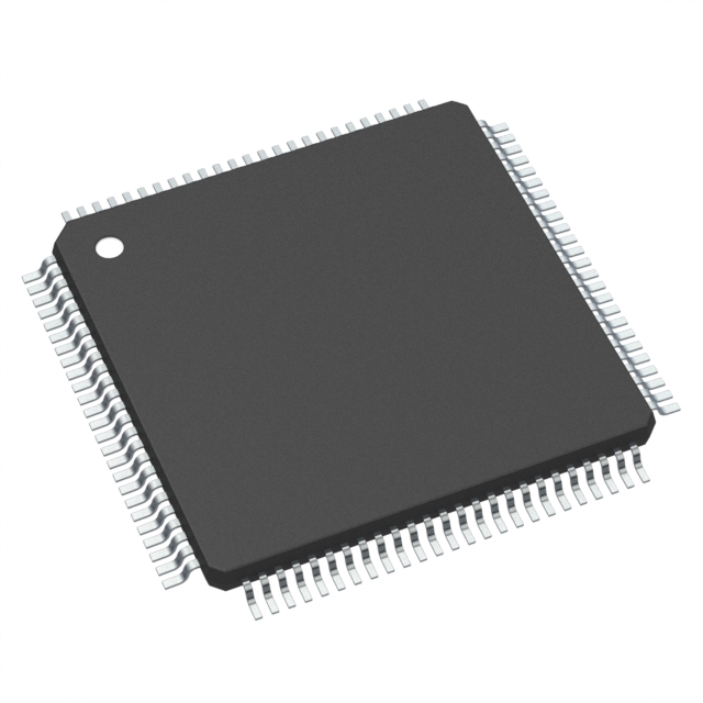 | 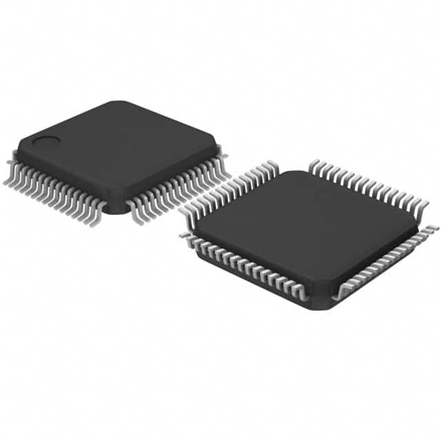 | 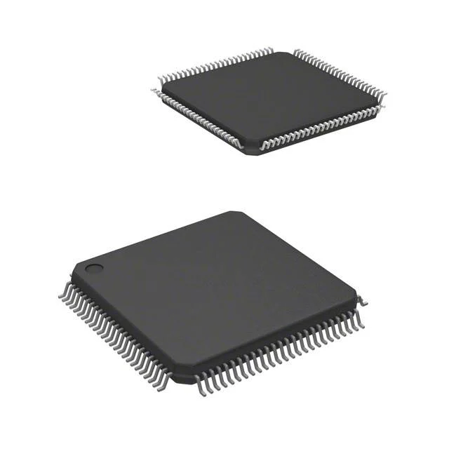 |  |  |
| Manufacturer | STMicroelectronics | STMicroelectronics | STMicroelectronics | STMicroelectronics | STMicroelectronics |
| Core Processor | ARM® Cortex®-M4 | ARM® Cortex®-M4 | ARM® Cortex®-M4 | ARM® Cortex®-M4 | ARM® Cortex®-M7 |
| Package / Case | 100-LQFP | 64-LQFP | 100-LQFP | 100-LQFP | 100-LQFP |
| Connectivity | CANbus, EBI/EMI, Ethernet, I²C, IrDA, LINbus, SAI, SDIO, SPI, UART/USART, USB, USB OTG | CANbus, I²C, IrDA, LINbus, MMC/SD, QSPI, SAI, SPI, SWPMI, UART/USART, USB OTG | EBI/EMI, I²C, IrDA, Memory Card, SPI, SSC, UART/USART, USB | CANbus, Ethernet, IrDA, MMC/SD, SPI, UART/USART, USB | CANbus, Ethernet, I²C, IrDA, LINbus, MMC/SD/SDIO, SPI, UART/USART, USB |
| Number of I/ O | 71 | 51 | 79 | 79 | 75 |
| Peripherals | Brown-out Detect/Reset, DMA, I²S, LCD, POR, PWM, WDT | Brown-out Detect/Reset, DMA, LCD, PWM, WDT | Brown-out Detect/Reset, DMA, POR, PWM, WDT | Brown-out Detect/Reset, DMA, POR, PWM, WDT | Brown-out Detect/Reset, DMA, I²S, POR, PWM, WDT |
| Speed | 180MHz | 80MHz | 120MHz | 120MHz | 300MHz |
| RAM Size | 384K x 8 | 128K x 8 | 128K x 8 | 128K x 8 | 384K x 8 |
| Program Memory Size | 1MB (1M x 8) | 1MB (1M x 8) | 1MB (1M x 8) | 1MB (1M x 8) | 1MB (1M x 8) |
| Data Converters | A/D 14x12b; D/A 2x12b | A/D 16x12b; D/A 2x12b | A/D 16x12b; D/A 2x12b | A/D 16x12b; D/A 2x12b | A/D 10x12b; D/A 2x12b |
| Mounting Type | Surface Mount | Surface Mount | Surface Mount | Surface Mount | Surface Mount |
| Voltage - Supply ( Vcc/ Vdd) | 1.7V ~ 3.6V | 1.71V ~ 3.6V | 1.62V ~ 3.6V | 1.62V ~ 3.6V | 1.62V ~ 3.6V |
| Operating Temperature | -40°C ~ 85°C (TA) | -40°C ~ 85°C (TA) | -40°C ~ 85°C (TA) | -40°C ~ 85°C (TA) | -40°C ~ 105°C (TA) |
STM32F469VGT6 Datasheet PDF
STM32F469VGT6 FAQ
Q: How to build the development environment of STM32F469VGT6?
A: Usually, the STM32CubeMX tool officially provided by STMicroelectronics can be used to generate the initialization code framework, which can easily configure the chip's pins, peripherals and other parameters. Development tools can be selected from integrated development environments (IDEs) such as Keil MDK and IAR Embedded Workbench. Import the code generated by STM32CubeMX into the IDE, and then develop it in combination with the corresponding compiler and debugger. At the same time, you also need to install the ST-Link driver for program download and debugging.
Q: How to program the STM32F469VGT6?
A: You can use C or C++ language for programming. First, configure the hardware parameters through STM32CubeMX and generate initialization code. Then write the application code in the IDE and use the STM32 standard peripheral library or HAL library (hardware abstraction layer library) to operate various peripherals of the chip, such as GPIO, UART, SPI, etc. After writing, compile and link, and finally download the program to the chip through debugging tools such as ST-Link to run it.
Q: How to use the graphics processing function of the STM32F469VGT6?
A: The chip integrates Chrom - ART Accelerator graphics hardware accelerator and LCD controller. When using, first configure the LCD interface (such as parallel interface or MIPI DSI) and related parameters through STM32CubeMX. In the code, use the functions provided by the HAL library to initialize the LCD controller and graphics accelerator. You can use graphics libraries (such as STemWin) to create graphical interfaces to implement functions such as windows, buttons, and text display, or you can directly operate the video memory to draw graphics and images.
Q: Can the operating frequency of STM32F469VGT6 be stable at 180MHz?
A: It can work stably at 180MHz under suitable hardware conditions. It is necessary to ensure that the power supply is stable, provide the chip with suitable voltage and good power supply filtering. At the same time, pay attention to the heat dissipation of the chip. Excessive temperature may affect the performance of the chip and even cause unstable operation. In addition, the quality and stability of the external crystal oscillator will also affect the operating frequency of the chip.
Q: Can the memory capacity of the chip be expanded?
A: The chip's own flash and SRAM capacity is fixed, but memory can be increased through external expansion. For example, you can expand program storage space by connecting an external SPI Flash through the SPI interface, or expand data storage space by connecting an external SRAM or SDRAM through the FSMC (static memory controller) interface. However, memory expansion requires additional hardware design and programming to implement data read and write operations.
Q: Can multiple communication interfaces of STM32F469VGT6 be used simultaneously?
A: Yes. These communication interfaces are independent of each other in hardware. As long as they are reasonably configured and managed during software programming, multiple interfaces can be used for data communication at the same time. For example, you can use UART to communicate with serial devices, SPI to communicate with external sensors, and USB to transfer data with computers. But be careful to avoid resource conflicts between different interfaces, such as pin multiplexing.
Q: How to use the ADC function of this chip for data acquisition?
A: First, use STM32CubeMX to configure ADC parameters, such as resolution, sampling time, channel selection, etc. In the code, call the ADC initialization function provided by the HAL library for initialization. Then you can start the ADC conversion by using the HAL_ADC_Start function to start the conversion, then use the HAL_ADC_PollForConversion function to wait for the conversion to complete, and finally use the HAL_ADC_GetValue function to get the converted digital value. It can be set to single conversion mode or continuous conversion mode as needed.
Q: What are the key points in the power supply circuit design of STM32F469VGT6?
A: The power supply circuit design is very critical. A suitable power supply chip is required to convert the external power supply into the 1.7V - 3.6V operating voltage required by the chip. Filter capacitors, such as large-capacity electrolytic capacitors and small-capacity ceramic capacitors, should be added to the power input to filter out ripples and noise in the power supply. At the same time, pay attention to the decoupling design of the power supply, and provide independent power supply filtering for different peripherals and core parts to avoid mutual interference. For some peripherals that have high requirements for power supply stability, LDO (low-dropout linear regulator) can also be used to further stabilize the power supply.
Q: What precautions should be taken for STM32F469VGT6 in PCB design?
A: When designing PCB, pay attention to reasonable layout. Connect the power pin and ground pin of the chip to the power layer and ground layer nearby to reduce the impedance of the power supply and ground. For high-speed signals (such as clock signals, communication interface signals, etc.), impedance matching should be performed to avoid signal reflection. At the same time, attention should be paid to the partitioning of different functional modules, such as the layout of analog circuits and digital circuits separately to reduce mutual interference. In addition, sufficient heat dissipation space should be left for the chip, and a heat sink can be added if necessary.
STMicroelectronics
在庫 : 4600